How to chip your OBD0 ECU.��� By Ben Ogle
Before doing this I would suggest you read the OBD0 Honda ECU basics first.
Chipping is pretty easy to do and, contrary to popular belief, does not really take much soldering skill. The actual soldering part is the easiest part of all. You really only need a steady hand, a few cheap tools, and a couple of parts.
Here's the need list in order:
A chippable OBD0 ECU (click here to make sure you have a chippable ecu)
A Phillips screw driver
Something to de-solder with
Some needle nose pliers
A beer
Something to pry the chip up with
A socket and a chip that is known to work (your stock one works if you don't burn it up)
A soldering iron and some solder
Another beer
First you take both the top and bottom covers off the ECU with your Phillips screw driver. If you are able to do this without too much thought then you are able to chip an ECU.
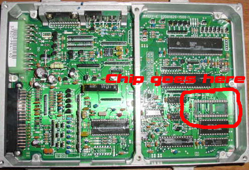
Then you locate the chip. It is on the opposite side of the board as the plugs and is a 28 pin bastard. Look at the pic, it's the circled one:
Now you have to de-solder that chip. This is the hardest part of the whole process. To do this you need a de-soldering tool. If you don't own one you have 2 options. You can go to radio-shack and either buy a de-soldering iron for $7, or you can buy some de-soldering braid for $5. I bought both but have not been able to get the braid to work. If you are able to use the braid, good, use it. The de-soldering iron looks like this:
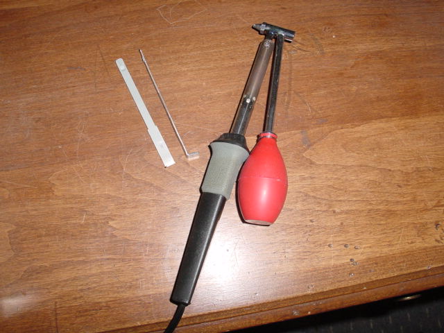
Look at the pic of the iron for a few seconds and you will realize how it works.
So now you own a de-soldering method. Find the chip on the bottom of the board and start de-soldering. I put the iron on there and wiggle the pin back and forth a little so I know that the solder is melted. Then I suck it up. You may not get all the solder out on some of the pins so you have to re-solder that pin and suck it up once again.
My advice on de-soldering is to NOT solder all the pins before you de-solder. I did this once because the newer solder sucks up nicer (more completely) than the old stuff on there. But what I didn't realize is that it penetrates more when you solder it. So when I went to pull the chip off I pulled up some traces. It sucked. Good thing it was a cheap ECU (and that I had some super glue, heh).
Now, once you have ALL the holes very clear you go and find your needle nose pliers. Take the pliers and wiggle each pin back and forth, to and fro (on the bottom side of the chip) to bust all the extra solder that the iron didn't get (you cant get it all). This is not a necessary step but I find that the chips come out easier.
The next step is to pull out the chip. This can be kind of a pain too (they glue the chips down) but its not too hard usually. I have tried all kinds of screw drivers, homemade devices, and even hair clips but the only thing that really gets them out is stereo keys. Yes those little bent pieces of metal that came in the box with your deck. If you go back up to the pic of the de-soldering iron you will see them in there too. Use the short end (duh) and pry the chip out. If it isn't semi-easy to pull out then go back and do the wiggle the pin thing with your pliers. Just make sure you don't pull up any traces. It sucks.
Once the chip is out you gotta put your socket in. Here is a pic of the 2 different kinds of sockets:
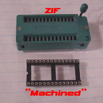
I always use the machined sockets because they are cheap and available. The ZIF (zero insertion force, like your girlfriend, heh) sockets are around $7 and the machined ones are like $1. I don't know if regular ZIF sockets like the one shown fit under the cover. They do sell low profile ZIF sockets so you may want to look into getting one of those. Either way, if you get a ZIF socket, make sure it fits under the top cover before you solder it in. They are a bitch to de-solder.
Put the socket of choice on the board and solder it in. Make sure the solder penetrates to both sides of the board.
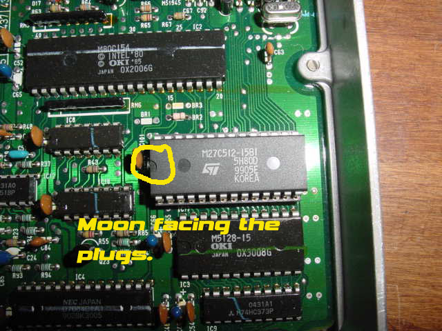
Now put in a chip that you know works. The chips have to go in a certain way. The little moon looking thing faces toward the plug sockets (and the same way as the rest of the moons on the board). If you put it in backwards I'm sure something bad will happen, and at the very least it wont work. Here is a pic of the moon and stuff:
Put the covers back on (or at least the bottom one) and go try it in your car. Plug in the ECU and start up the car without touching the gas. Watch the engine light to see if it comes on. If the CEL comes on and the ECU led is a solid red light you have to try a different chip. If you didn't fry the stock chip (I never have so I don't know if its easy to do or not) or completely mess up the pins you can try it in there. If the ECU blinks, count the blinks and check what code it is here.
If it works then good job. See, it was easier than people say wasn't it?
As a side note, I use the stereo keys to pull the chip out of the socket too. It works a hell of a lot better than your fingers. I have ruined a chip or 2 by pulling them out with my fingers because they come out all of a sudden and then I end up bending or breaking pins. So now I always use the keys. You could also use a chip puller. I am sure they are cheap at an electronics shop.
If you didn't drink those beers yet then go drive your car. If they are long gone watch some TV. :)
Home